
NIF released positive data. Is some unexpected effect is blocking full success?
The staff of the National Ignition Facility (NIF) in Livermore California released papers on very positive new results in their work toward inertial confinement fusion (ICF). NIF is on a success path, and they need to continue doing what they just did, but more so. This will actualize the potential for 5 MJ power output/target shot, as required for true success.
This is our 3rd post in this thread. NIF results discussed in Parts 1 and 2:
- Gain: Target implosions produced about as much energy as was applied.
- Enhanced heating: The fusion reaction is starting to cause more fusion. First step towards an ignited plasma core.
- Not in-control: The stagnation core at the end of the implosion is an inefficient donut with hard peanuts on one side, should be a plum with a hard/hot central core
We continue our discussion by looking at what might have been helped by their new operating changes. This is a “popular” discussion, not a truly technical one, but we must get through some of the technical points if we want to understand.
Click any image to expand to full size.
Overview: Beams on Target
Table A outlines specifications for a NIF laser, hohlraum and target.
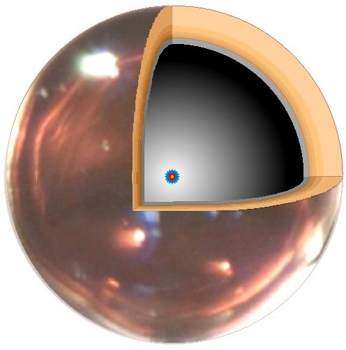
Fig 1 Target shell cutaway. Compressed core is shown at the center (red)

Tbl A Specifications for Target, hohlraum, Beams
Fig 1 is an image of the target, less than 1/8″ in diameter.
- The ablating shell (called the pusher) has a complex construction of 5 plastic layers to provide density gradation between laser and the fuel layer.
- The inner layer (gray) is the deuterium/tritium fuel mix frozen onto the inner shell in a layer about 3 thousands of an inch thick.
- The compressed core is shown in the center, drawn in as the red circle.
- The central void is mostly vacuum, except the thin DT gas that has evaporated from the inner surface.
The target must hold together and collapse smoothly during the extreme environment of the implosion. What researches must do is smoothly guide the target plasma (something like an arc welding “flame,” but thousands of times hotter) into a smooth core.

Tbl B Extreme target environments
Table B lists several of the severe conditions they must deal with.
- To reach the bang-point while the laser is on, it must be pushed smoothly with a trillion times more force than Earth’s gravitational field.
- It will be in the plasma state but must be moving at 10 million cm/sec, 5 to 10 faster than most plasma acceleration schemes in current use.
- The shell blows off but it must be evenly removed over the surface, not like a space craft’s re-entry. The shell should be mostly used up by Bang-Time, but the ablation front must not burn through to the fuel layer.
We will look at NIF using a very simple model, the kind called “back of the envelope.”
About modeling with calculations: Models extrapolate what would happen if everything works as expected , but doing new things is hard because of unexpected events happen. So my guiding idea is to check feasibility with simple estimates first; if the simple estimate are good, then do the detailed computer modeling.
Our point:
if simple estimates say …
… it will not work. It probably won’t. But cross check your findings!
… it is “iffy” – maybe it is possible. Try it but don’t start by pushing the boundaries.
… it definitely will work. Go for it! Expect tension and high stress to make it go.
Computation is worthwhile, but over-the-top detailed models do not reveal the actual truth. Consider this slight misquote from General Semantics: The map is not the territory, the calculation is not the thing.
The data and the simple criteria

Fig 2: New HF and old LF Shot sequences
Shorter shot time What the NIF managers did is shown in Fig 2. The shot length was reduced from from 25 to 15 ns and the power was raised in the trough leading to the ramp-up of laser energy.
This new method is called the “high foot” (HF) mode of operation. (A nanosecond is 1 billionth (US) of a second. Light moves about a foot ··· 30cm ··· in 1 ns.)
Their change pushes the same energy as before into the target, but faster … 870 GW instead of the previous 520 GW.
Are the laser beams misaligned – or blocked?

Fig 3 1995 Nova data. RT spikes 0r beam-target instabilities?
Fig 3 an x-ray image of a target implosion from the large Nova laser, predecessor to NIF. The image exposure time is (about) 1/3 nanosecond.
We see strong speckle because there are not many photons available in short a time.
Wikipedia calls these images of the RT instability inside a target. (We discuss RT in part 4 of this blog thread.)

Fig 4 Nova hohlraum with the 12 laser beam hit points
These 12 spikes in the images do not look like RT inside a target. Fig 4 shows the Nova hohlraum with this 12 hit points.
Looks to us as that the spikes in Fig 3 are plasma jets from the hit points.
Does beam-on-metal data help make things clear? One of our last studies at KMS Fusion focused the intense laser beams on flat gold plates.

Fig 5 Cold jet from beam on Au
Fig 5 was taken by our imaging holographic interferometer; 1 of 4 images, 1/3 ns exposure.
Result – we observed cold dense plasma jets from the strike spot, originating between the hot spots in the laser beam: high density (1020 g/mL) objects moving from the target surface at plasma expansion speeds (> 106 cm/s). Our working model: higher intensity beam regions pushed the plasma jets up and out from the lower intensity and cold nearby regions , similar to squeezing a tube of toothpaste.

Tbl C Jet size, assuming sonic velocity
Table C shows estimates the size of a beam-plasma jet at the end of a NIF pulse. Our model is of a jet expanding at about the plasma speed of sound, as in the KMS data.
Fig 6 shows the NIF situation: many beam hit points on the walls. Jets could occur between beam strike points (if close enough) or in any one of the hit areas, between the hot spots.

Fig 6 NIF hohlraum with beam hit points
If jets are a real phenomenon, they are most likely to form in the equatorial band where beams from the two ends overlap (see Part 2, Fig 2).
The target is separated from the hohlraum wall by 1.75 mm (Table A). The coldest estimate for the plasma indicates that a jet will have crossed about 1/3 of the original distance. Such jets would change laser beam and x-ray propagation in the chamber, change the distribution of intensities; they could affect the heating of the target.
Blockage by cold jets is a hypothetical process. I have not read of one discussing such a possibility – no one (else) has indicted the hohlraum of misbehavior, but Nova data seems to show the event and NIF geometry invites it.
Is shell burn-through possible?

Fig 7 Imploding target with beam breakthrough. Blue is x-ray drive illumination.
What if uneven shell erosion is driven by hot spots in the driving illumination? Is this a question too basic and simple to ask? The the ablation process ought to move through the solid shell at the speed of sound (in the shell material). But what if shell erosion is boosted by interactions between the shell wall and the beam intensity? Fig 7 shows the implosion issue.
The fuel perturbation were sketched as a bulge toward the center, but it might well be an depression in the ID.
NIF results looks like square donuts, not the intended spherical billiards ball. Meaning: yes, there are irregularities in the illumination. Look again at Fig 1. If the driving light is not symmetrical and uniform, the smooth sphere will immediately be cratered like the surface of the moon. Once formed, these craters do not vanish but grow proportionately deeper.

Tbl D Time for drive beam to punch through the target shell, into the fuel
Bright spots imprint dents into the pusher shell that do not disappear during collapse – one of the messages from a presentation by a member of Stephen Bodner’s NRL team (Nov 1988).
Table D shows estimates of the time needed for a deeper-than-normal crater to reach the inner fuel layer, assuming the pit propagates inwards at sound speed.
The estimates are for sound speed expansion in through a plasma, and show no joy. Hotter than 20 eV might be a bit too hot; 2 eV is the temperature of an arc welder – it is a bit too cold.
Pusher shell burn-through is regime where the estimates are ambiguous. A cold pusher shell (2 eV case) indicates that the 25 ns original shots were probably too long and current 15 ns pulse lengths are possibly so. If the beam is hotter than shown on the table, the ambiguity goes away; the pusher shell would be burned away in even the best scenario and the last nanoseconds are about ablating fuel. Bad idea.
So…
We have done “back of the envelope” estimates for 2 possible reasons that the NIF shots, good as they were, did not do better.
LLNL has some of the wold leaders in detailed modeling, it is inconceivable that they would not have simulated any foreseeable issue in implosion physics. They are masters at target design, just look at the actual complex target – it takes real skill to design and assemble such a multilayer shell. Could they have missed any normal occurrence? Not likely.
The performance limiter must be something arising from an unexpected direction. These are just guesses without sufficient access to data (or computation power) to put more depth into them.
Things have gone horribly wrong for NIF these past 5 years. They are working their way out of the depressing pit and toward success. The next post in this thread will discuss the important RT instability and will do an overall summary of the result.
………………………………
Charles J. Armentrout, Ann Arbor
2014 Jun 6 Update Jun 7 to correct several typographical errors
Listed under Technology … Technology > ICF/IFE
Have a comment? Click on the title of this post, go to bottom, let us know.
Related posts: Click the INDEX button under the Banner picture
